 English
 русский
 Français
 Español
 عربى
عربىLQ-RRTO Роторное тепло хранение высокотемпературного сжигания
Оборудование
Обзор RTO-типа башня Наша компания предлагает два типа ROTARY RTO, которые представляют собой ROTARY RTO и одноклассный RTO с одной бочкой....
Смотрите детали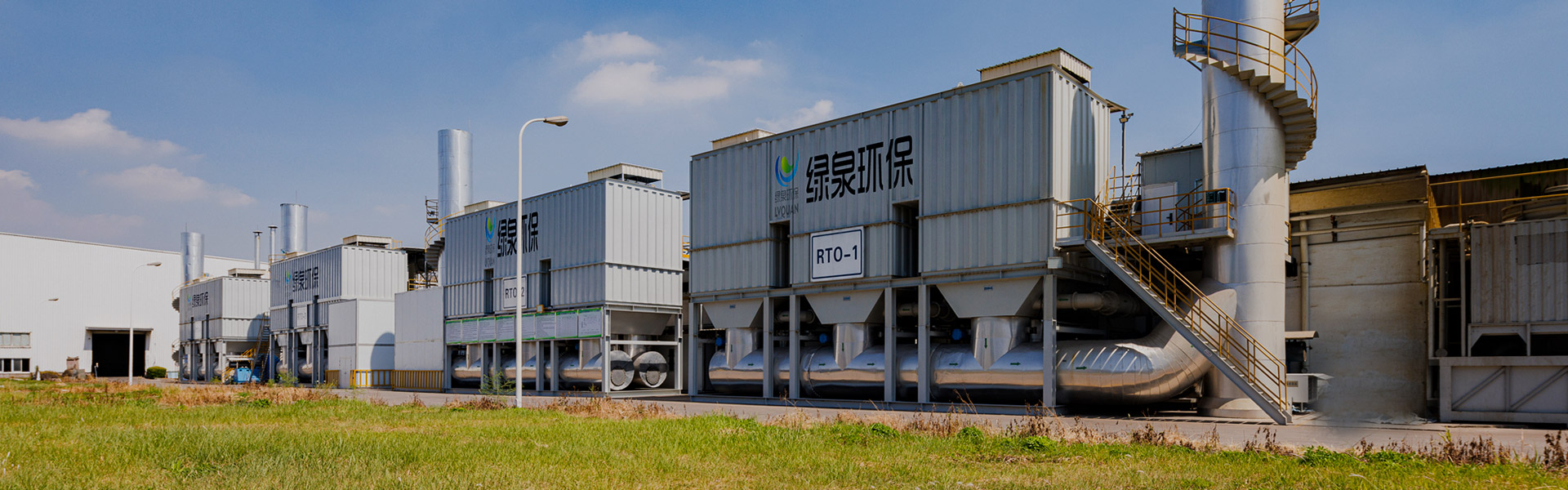
Контент
Для низкие концентрации ЛОС (ниже 1000 мг/м³) Адсорбция активированным углем является наиболее экономичным выбором. Для средние концентрации (1000–3000 мг/м³) , каталитическое сжигание (CO) обеспечивает оптимальную эффективность. Для потоки с высокой концентрацией выше 3000 мг/м³ или сложные смеси Регенеративные термические окислители (РТО) обеспечивают превосходную эффективность разрушения, превышающую 99%.
Основным критерием выбора является нижний предел взрываемости (НПВ). Когда концентрация ЛОС превышает 25% НПВ RTO становится обязательным для соблюдения требований безопасности. Ниже этого порога оптимальную технологию определяют эксплуатационные затраты и требования к эффективности уничтожения.
Эта технология работает посредством физической адсорбции, улавливая молекулы ЛОС на пористых углеродных поверхностях. Он превосходно справляется с управлением прерывистые потоки низкой концентрации (50–1000 мг/м³) с первоначальными капитальными затратами на 40–60% ниже чем системы термического окисления. Однако он генерирует вторичные отходы — отработанный углерод, требующий утилизации или регенерации — и не может эффективно обрабатывать потоки с высокой влажностью или частицами.
В каталитических системах используются катализаторы из драгоценных металлов (обычно платина или палладий) для окисления ЛОС при 300–500°С , значительно ниже, чем при термическом окислении. Это снижает расход топлива на 60–80% по сравнению с прямым сжиганием. Идеально подходит для непрерывной работы с постоянными потоками средней концентрации. Деактивация катализатора соединениями кремния, серы или галогена представляет собой основной эксплуатационный риск.
RTO достигают термического КПД до 95–97% через керамические теплообменники, которые рекуперируют тепло сгорания. Диапазон рабочих температур от 760–1100 °С , обеспечивая полное окисление даже сложных смесей ЛОС. Хотя капитальные вложения самые высокие ( 150 000–500 000 долларов США для стандартных установок), эксплуатационные затраты снижаются при более высоких концентрациях благодаря автотермическому режиму, при котором сжигание ЛОС поддерживает процесс без дополнительного топлива.
| Параметр | Активированный уголь | Каталитическое сжигание | RTO |
|---|---|---|---|
| Оптимальная концентрация | < 1000 мг/м³ | 1000–3000 мг/м³ | > 3000 мг/м³ |
| Рабочая температура | Эмбиент | 300–500°С | 760–1100 °С |
| Эффективность разрушения | 90–95% | 95–99% | 99–99,9% |
| Относительная капитальная стоимость | Низкий (1,0x) | Средний (2,5x) | Высокий (3,5x) |
| Вторичные отходы | Отработанный углерод | Нет | Нет |
Молекулярная структура ЛОС напрямую влияет на возможность очистки. Соединения, содержащие хлор, сера или кремний будет отравлять катализаторы в системах CO в пределах 200–500 часов работы . Бензол, толуол и ксилол (БТК) превосходно реагируют на термическое окисление, тогда как кислородсодержащие соединения, такие как ацетон, требуют более длительного времени пребывания. Галогенированные углеводороды требуют использования скрубберов последующей обработки для удаления кислых газов, образующихся при сжигании.
Проектная мощность должна обеспечивать пиковые расходы с Запас прочности 15–20 % . Системы RTO допускают изменения расхода на ±20% без значительной потери эффективности, тогда как каталитические системы требуют стабильного потока для оптимальной рекуперации тепла. Слои с активированным углем сталкиваются с риском образования каналов, когда скорость потока падает ниже 60% проектной мощности .
Входные потоки должны содержать менее 5 мг/м³ твердых частиц и относительная влажность ниже 50% для систем углеродной адсорбции. RTO могут обрабатывать до 30 мг/м³ твердых частиц но для более высоких нагрузок требуется предварительная фильтрация. Содержание влаги выше 15% по объему значительно снижает адсорбционную способность и может вызвать необходимость осушения на входе.
Местные ограничения на выбросы диктуют требования к эффективности уничтожения. В Соединенных Штатах стандарты максимально достижимой технологии управления (MACT) Агентства по охране окружающей среды часто требуют Эффективность разрушения 99% , требуя RTO или высокопроизводительных систем CO. Пороговые значения Европейской директивы о промышленных выбросах (IED) различаются в зависимости от соединения, при этом предельные значения бензола составляют 5 мг/м³ и total VOC at 20 мг/м³ .
Революционные выбросы происходят, когда углерод достигает насыщения — обнаруживается, когда концентрации на выходе превышают 10% от входного уровня . Обычно это происходит после 2000–8000 часов в зависимости от загрузки ЛОС. Постельные пожары возникают в результате экзотермической адсорбции кетонов или недостаточного охлаждения; температура выше 150°С в слое углерода указывают на неизбежный риск возгорания.
Деактивация катализатора проявляется как увеличение концентрации на выходе или повышение требуемой рабочей температуры . Повышение температуры на 50°C выше исходного уровня указывает на 30% потерю активности катализатора. Термический удар от резких перепадов температуры (> 100°C/час) вызывает разрушение структуры носителя катализатора. Предпусковые подогреватели не достигают минимум 350°C приводят к неполному окислению и опасному накоплению летучих органических соединений.
Керамическая пробка среды снижает тепловой КПД ниже 85% , что можно обнаружить по увеличению расхода топлива. Падение давления на теплообменнике не должно превышать 15 дюймов водяного столба ; более высокие значения указывают на блокировку. Неисправности уплотнений клапанов вызвать перекрестное загрязнение между входом и выходом, снижая кажущуюся эффективность разрушения при сохранении температуры в камере сгорания.
| Неисправность | Предупреждающий знак | Критический порог | Немедленное действие |
|---|---|---|---|
| Угольный слой огня | Повышение температуры слоя | > 150°С | Аварийная продувка азотом |
| Отравление катализатором | Повышенное содержание ЛОС на выходе | > 50 частей на миллион на выходе | Заменить слой катализатора |
| Подключение среды RTO | Высокое падение давления | > 15 дюймов H₂O | Очистка/замена носителя |
| Недостаточное окисление | Низкая температура в камере | < 760°C (RTO) | Увеличьте расход топлива |
Операторы должны проверить перепады давления на входе и выходе , запишите температуру камеры сгорания и проверьте видимые компоненты на предмет утечек или коррозии. Для углеродных систем ежедневный мониторинг прорывные системы обнаружения является обязательным. Все показания должны отклоняться менее чем на 5% от базового уровня значения, установленные при вводе в эксплуатацию.
Провести детальную проверку приводы и уплотнения клапанов в системах RTO — замените уплотнения, если износ превышает 2 мм . В случае каталитических блоков проверьте подогреватели на наличие горячих точек, указывающих на неисправность элемента. Углеродные системы требуют отбор проб пласта определить остаточную адсорбционную емкость; йодные числа ниже 600 мг/г указать необходимость замены.
Ежеквартальные мероприятия включают в себя полная проверка СМИ в установках РТО, испытания активности катализаторов в системах СО и замена углерода в адсорбционных системах переработки высокомолекулярных соединений. Ежегодное техническое обслуживание включает проверку огнеупоров, настройку горелки на оптимальную работу. 3% избыток кислорода и комплексная проверка системы контроля. Бюджет примерно 8–12% от первоначальных капитальных затрат ежегодно за ремонтные материалы и рабочую силу.
Да. Гибридные системы концентратор-RTO используйте цеолитовые или угольные колеса для концентрации потоков с низким содержанием летучих органических соединений (50–500 мг/м³) путем Соотношения от 10:1 до 20:1 перед термическим окислением. Эта конфигурация снижает расход топлива RTO на 70–90% по сравнению с прямой обработкой разбавленных потоков. Аналогично, адсорбция углерода с регенерацией пара, питающая каталитическое сжигание, справляется с периодическими пиками высоких концентраций.
При концентрациях ЛОС выше 2500 мг/м³ , системы RTO окупаются в течение 18–30 месяцев за счет экономии топлива, несмотря на более высокие капитальные затраты. Каталитическое сжигание обеспечивает более быструю окупаемость ( 12–18 месяцев ) при средних концентрациях, когда долговечность катализатора превышает 3 года . Ниже 1500 мг/м³ активированный уголь остается наиболее экономически эффективным в течение 10-летний жизненный цикл .
Установить буферные резервуары или уравнительные сосуды для смягчения скачков концентрации. Для систем RTO реализуйте байпас горячего газа для отвода избыточного тепла, когда концентрации превышают автотермические условия. Каталитические системы требуют впрыск разбавляющего воздуха для поддержания концентрации на входе ниже 25% НПВ . Системы с активированным углем лучше всего переносят изменения, но требуют большие кровати выдерживать пиковые нагрузки без прорывов.
Галогенированные соединения требуют термические окислители с закалочными колоннами и скрубберами кислого газа . RTO можно адаптировать с помощью устойчивый к коррозии керамический материал и downstream caustic scrubbers to remove HCl or HF. Alternatively, рекуперативные термические окислители (нерегенеративные) обеспечивают более простую интеграцию с системами мокрой очистки для небольших масштабов.
Все системы термического окисления требуют Мониторы НПВ с автоматическим отключением топлива в 25% НПВ (или 50 % с элементами управления с рейтингом SIL ). Отключения при высокой температуре срабатывают при 1200°С для МРК. Углеродные системы нуждаются детекторы угарного газа в верхних пространствах сосудов и системы продувки азотом для тушения пожара. Аварийные вентиляционные отверстия должны выдерживать 150 % от максимального ожидаемого расхода .

Обзор RTO-типа башня Наша компания предлагает два типа ROTARY RTO, которые представляют собой ROTARY RTO и одноклассный RTO с одной бочкой....
Смотрите детали
Обзор Каталитическое сжигание - это метод очистки, который использует катализаторы для окисления и разложения горючих веществ в выхлопных г...
Смотрите детали")
Обзор витрины с переменной свободной платой Верворет концентрации цеолита нашей компании использует комбинацию модулей цеолита, с высоким с...
Смотрите детали
Обзор активированного углеродного волокничного устройства для очистки органического растворителя Активированная система очистки органич...
Смотрите детали
Обзор Оборудование для очистки и восстановления в серии VOC-ACA используется для поглощения, восстановления и повторного использования газо...
Смотрите детали
Введение продукта Газовый теплообменник в основном используется для отраслей энергосбережения и сокращения выбросов при извлечении отработа...
Смотрите детали
Концепция системы rto цеолита RTO Используя цеолитное колесо для адсорбированного газа органических отходов, низкая концентрация и высокий ...
Смотрите детали")
Оборудование для каталитической очистки VOC-CFT-CO Адсорбционное оборудование для каталитической очистки VOC-CFT-CO-CO, состоящее из активи...
Смотрите детали + Термический окислитель (до)")
Концепция цеолитного колеса прямого сжигания высокотемпературное оборудование для сжигания Цель использования роторного барабанного цеолита...
Смотрите детали
Обзор Принцип снятия влажной пыли использует процесс захвата и разделения частиц пыли в газовой фазе путем полностью контактируя газо-жидко...
Смотрите деталиМобильный
Инструкция по эксплуатации продукта

Авторское право © LV Quan Environmental Protection Engineering Technology Co., Ltd.
